MagSafe Magnet Ring Dimensions and Customization Guide
MagSafe-style magnet rings are widely used in magnetic phone cases, wireless chargers, power banks, car mounts, charging stands, wallets, and other consumer-electronics accessories.
Although many magnet rings look similar, their dimensions and magnetic performance are not necessarily the same. Small differences in ring diameter, magnet thickness, segment position, adhesive, or polarity can affect:
- Phone alignment
- Magnetic holding force
- Wireless charging stability
- Product thickness
- Assembly accuracy
- Accessory compatibility
- User experience
This guide explains the main dimensions of a MagSafe magnet ring, which parameters can be customized, and what information buyers should provide when developing a custom magnetic assembly.
Quick Answer: What Dimensions Define a MagSafe Magnet Ring?
The main dimensions normally include:
- Outer diameter
- Inner diameter
- Magnet radial width
- Magnet thickness
- Total assembly thickness
- Number of magnet segments
- Segment length and width
- Gap between segments
- Orientation-magnet dimensions
- Distance between the ring and orientation magnet
- Carrier thickness
- Adhesive thickness
- Concentricity
- Flatness
- Position tolerance
There is no single commercially available magnet-ring size suitable for every MagSafe-style or Qi2-related product.
The final dimensions should be selected according to the product housing, charging-coil position, required holding force, working air gap, temperature, and compatibility target.
What Is a MagSafe Magnet Ring?
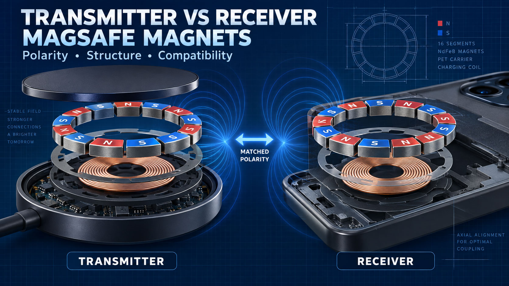
A MagSafe magnet ring is a circular magnetic assembly used to align and attach a phone or accessory.
It normally consists of:
- Multiple neodymium magnet segments
- A circular carrier
- An adhesive layer
- A release liner
- An optional orientation magnet
- An optional steel or magnetic back plate
The ring helps position the charging coils and provides mechanical attachment. It does not generate or transmit wireless charging power by itself.
In many products, a separate orientation magnet is added below the main ring. This helps control the rotational position of accessories such as wallets, stands, and power banks.
Are All MagSafe Magnet Rings the Same Size?
No.
Many standard rings sold in the market use similar general layouts, but dimensions can vary between manufacturers and applications.
Differences may include:
- Ring outer diameter
- Ring inner diameter
- Magnet thickness
- Segment quantity
- Segment width
- Orientation-magnet size
- Carrier material
- Adhesive thickness
- Pole arrangement
- Magnetic grade
- Holding force
A ring that fits one phone case may not fit another wireless charger or power bank.
For OEM and ODM projects, buyers should not rely only on a supplier’s statement that a ring is “standard MagSafe size.” The drawing and actual dimensions should be confirmed before sampling.
Common Reference Dimensions
Commercial MagSafe-style magnetic rings often fall within the following general reference ranges:
| Parameter |
Common market reference |
| Ring outer diameter |
Approximately 54–56 mm |
| Ring inner diameter |
Approximately 44–46 mm |
| Radial magnetic width |
Approximately 4–6 mm |
| Magnet thickness |
Approximately 0.5–2.0 mm |
| Number of ring segments |
Commonly 16–20 pieces |
| Total assembly thickness |
Depends on magnet, carrier, adhesive, and cover |
| Orientation magnet |
Customized according to product layout |
| Segment gap |
Determined by polarity, assembly, and dimensional design |
These are general commercial reference ranges—not universal Apple, MagSafe, or Qi2 certification dimensions.
The correct dimensions must be confirmed using:
- The latest applicable technical requirements
- The actual product drawing
- The charging-coil location
- Prototype testing
- Required ecosystem or certification rules
For products intended for Apple’s MagSafe ecosystem, developers should review the current Apple accessory requirements. For Qi2 products, applicable requirements should be confirmed through the Wireless Power Consortium and its authorized testing process.
Important Dimensions to Specify
1. Outer Diameter
The outer diameter determines the total space required by the magnetic ring.
It affects:
- Product housing size
- Available PCB and battery space
- Charging-coil positioning
- Camera clearance
- Edge clearance
- Magnetic contact area
A larger outer diameter may increase the available magnetic area, but it also requires more internal space.
The outer diameter must not interfere with:
- Camera modules
- Battery structures
- Circuit boards
- Housing ribs
- Screws
- Wireless charging coils
- NFC antennas
- Other sensors
2. Inner Diameter
The inner diameter defines the open area inside the magnetic ring.
This space may contain:
- Wireless charging coil
- Ferrite shielding
- NFC components
- Sensors
- Structural supports
If the inner diameter is too small, the magnet ring may interfere with the charging coil or other components.
If it is too large, the magnetic ring may have less magnetic area or may not align correctly with the mating product.
The inner diameter should therefore be selected together with the coil and shielding design.
3. Radial Width
Radial width is the distance between the outer and inner edges of the ring.
It can be calculated approximately as:
Radial width=2Outer diameter−Inner diameter
Radial width affects:
- Magnet volume
- Available magnetic force
- Segment dimensions
- Product space
- Magnetic-field distribution
Increasing the width may increase magnetic material volume, but magnetic performance still depends on thickness, grade, pole arrangement, and the mating structure.
4. Magnet Thickness
Magnet thickness is one of the most important design parameters.
A thicker magnet may provide:
- Greater magnetic output
- Better holding force across an air gap
- More design flexibility
However, increasing thickness may also cause:
- A thicker finished product
- Higher material cost
- Housing interference
- Greater magnetic force than the user needs
- Assembly difficulty
The thinnest possible magnet is not always the best choice either. A magnet that is too thin may not provide enough force after adding the housing, adhesive, coating, and phone case.
The correct thickness should be determined through magnetic analysis and prototype testing.
5. Total Assembly Thickness
Magnet thickness and total assembly thickness are not the same.
Total assembly thickness may include:
- Magnet
- Magnet coating
- Carrier
- Adhesive
- Release film
- Back plate
- Plastic overmolding
- Protective cover
For example, a 1.0 mm magnet does not necessarily create a 1.0 mm finished magnetic assembly.
Buyers should specify both:
- Individual magnet thickness
- Maximum complete assembly thickness
This helps prevent problems when closing the housing or fitting the component into a limited internal space.
6. Number of Magnet Segments
A magnet ring is normally made from multiple individual magnet segments.
The segment quantity affects:
- Pole arrangement
- Magnetic-field distribution
- Assembly complexity
- Ring roundness
- Segment gap
- Production cost
- Holding-force uniformity
More segments can provide greater design flexibility, but they also increase assembly and polarity-control requirements.
The ideal quantity depends on:
- Ring diameter
- Magnet dimensions
- Pole pattern
- Product compatibility
- Manufacturing method
The buyer and supplier should approve a polarity drawing before sample production.
7. Segment Dimensions and Spacing
Each magnet segment should be defined by:
- Arc length
- Radial width
- Thickness
- Chamfer or corner shape
- Coating thickness
- Dimensional tolerance
The spacing between segments also matters.
Uneven spacing may cause:
- Uneven holding force
- Poor ring appearance
- Assembly imbalance
- Polarity-position errors
- Compatibility problems
For mass production, the supplier should control each segment position through a carrier, fixture, or automated assembly process.
8. Orientation-Magnet Dimensions
Many magnetic assemblies include an additional magnet below the main ring.
This orientation magnet may help:
- Prevent accessory rotation
- Define installation direction
- Improve wallet positioning
- Stabilize power banks or stands
- Create a more consistent user experience
Important parameters include:
- Orientation-magnet length
- Width
- Thickness
- Distance from the main ring
- Center position
- Pole direction
- Magnetic strength
The orientation magnet should not be designed independently from the ring. Its location and polarity must be evaluated as part of the complete magnetic system.
9. Carrier Dimensions
The carrier holds the individual magnet segments in position.
Common carrier materials include:
- PET
- PC
- ABS
- Other engineered plastics
- Pressure-sensitive adhesive structures
- Customized molded carriers
The carrier affects:
- Segment positioning
- Ring flatness
- Assembly speed
- Total thickness
- Adhesive bonding
- Product durability
A weak or inaccurate carrier may deform during transportation or assembly, causing the magnet segments to move.
Important carrier requirements include:
- Inner and outer diameter
- Thickness
- Material
- Position tolerance
- Temperature resistance
- Flatness
- Adhesive compatibility
10. Adhesive Thickness
Many magnetic rings are supplied with pre-applied adhesive.
The adhesive layer affects both total thickness and working air gap. Even a small increase in adhesive thickness may reduce the final magnetic force.
The adhesive should be selected according to:
- Housing material
- Surface texture
- Temperature
- Humidity
- Product lifetime
- Assembly pressure
- Required bonding strength
Common housing materials include:
- ABS
- Polycarbonate
- Glass
- Aluminum
- Stainless steel
- Painted surfaces
- Silicone
- Composite materials
Testing should be performed on the actual product surface whenever possible.
11. Concentricity and Position Tolerance
The magnetic ring must be positioned correctly relative to the wireless charging coil.
Important positioning requirements include:
- Ring-to-coil concentricity
- Ring-to-housing position
- Orientation-magnet location
- Segment-to-carrier position
- Complete assembly alignment
Poor concentricity may contribute to:
- Inconsistent attachment
- Charging misalignment
- Uneven magnetic force
- Cosmetic defects
- Compatibility problems
A professional drawing should define the center datum and positional tolerances.
12. Flatness
A magnetic ring should remain flat after assembly.
Poor flatness may create:
- Uneven contact
- Reduced holding force
- Housing bulging
- Adhesive failure
- Assembly gaps
- Product noise or movement
Flatness can be affected by:
- Magnet thickness variation
- Carrier deformation
- Uneven adhesive
- Segment positioning
- Packaging pressure
- Temperature
The supplier should inspect the complete ring rather than only checking individual magnet dimensions.
Dimensions That Can Be Customized
A professional magnetic assembly supplier can normally customize:
| Customization item |
Possible adjustment |
| Outer diameter |
Match available product space |
| Inner diameter |
Fit the charging coil and shielding |
| Magnet thickness |
Balance force and product thickness |
| Segment quantity |
Adjust magnetic layout and manufacturing method |
| Segment shape |
Arc, block, trapezoid, or custom geometry |
| Pole arrangement |
Match the intended mating product |
| Orientation magnet |
Adjust size, position, and polarity |
| Carrier |
PET, plastic, molded, or custom structure |
| Adhesive |
Selected for the actual housing material |
| Coating |
Nickel, zinc, epoxy, or custom protection |
| Magnet grade |
Selected for strength and temperature |
| Holding force |
Adjusted for the target user experience |
| Complete assembly |
Integrated with carrier, adhesive, or housing |
Customization should begin with the complete product requirement—not simply a desired magnet-ring diameter.
How Dimensions Affect Magnetic Force
The magnetic holding force is influenced by several dimensional factors.
Larger Magnetic Area
A wider ring or larger segment area may increase magnetic interaction, but the benefit depends on the mating structure and magnetic circuit.
Greater Magnet Thickness
Increasing thickness may increase magnetic output, especially when the original magnet is very thin. However, the improvement becomes smaller when the magnetic circuit approaches saturation.
Smaller Working Gap
Reducing the distance between the magnetic components is often one of the most effective ways to improve actual holding force.
Better Assembly Accuracy
Correct segment position, polarity, concentricity, and flatness can improve force consistency without changing the magnet grade.
For this reason, product designers should not rely only on upgrading from N48 to N52. Dimensional and structural optimization may provide better results.
How Dimensions Affect Wireless Charging
The magnet ring does not transfer charging power, but its dimensions and position can influence the complete charging system.
An unsuitable ring design may contribute to:
- Coil misalignment
- Increased working distance
- Unstable charging
- Additional heat
- Mechanical interference
- Sensor or NFC interference
- Foreign-object-detection problems
- Housing assembly problems
Wireless charging performance also depends on:
- Coil dimensions
- Coil position
- Ferrite shielding
- Control electronics
- Input power
- Thermal management
- Communication protocol
- Foreign-object detection
The complete product must therefore be tested as one integrated system.
Selecting the Right Magnet Thickness
Use the following general design logic:
Choose a thinner magnet when:
- Internal space is extremely limited
- Product thickness is a priority
- The working air gap is small
- The mating magnetic structure is strong
- Required holding force is moderate
Choose a thicker magnet when:
- The housing or phone case creates a larger gap
- Higher holding force is required
- The accessory is relatively heavy
- The product is used vertically
- Greater magnetic output is needed
The final thickness should be confirmed through sample testing. Increasing magnet thickness without considering the complete magnetic circuit may increase cost without producing the expected improvement.
Selecting the Magnet Grade
Common neodymium magnet grades may include:
- N35
- N42
- N48
- N50
- N52
- High-temperature grades such as H or SH series
A higher numerical grade normally indicates a higher maximum energy product, but it does not mean that it is always the best material.
Grade selection should consider:
- Required holding force
- Magnet dimensions
- Maximum temperature
- Demagnetization risk
- Working air gap
- Product lifetime
- Cost target
For wireless charging products exposed to higher temperatures, resistance to irreversible demagnetization may be more important than maximum room-temperature magnetic strength.
Coating and Corrosion Protection
Sintered NdFeB magnets can corrode without suitable surface protection.
Common coatings include:
- Nickel-copper-nickel
- Zinc
- Epoxy
- Nickel plus epoxy
- Parylene
- Customized protective coatings
The selected coating may slightly affect magnet dimensions and assembly tolerance.
Coating selection should consider:
- Humidity
- Temperature cycling
- Salt exposure
- Adhesive compatibility
- Wear and friction
- Product lifetime
- Cosmetic requirements
For demanding environments, coating alone may not be sufficient. Plastic overmolding, sealing, or encapsulation may be required.
Recommended Dimension-Control Items
A custom magnet-ring drawing should include:
- Outer diameter tolerance
- Inner diameter tolerance
- Magnet thickness tolerance
- Total assembly thickness
- Segment position tolerance
- Segment gap tolerance
- Ring concentricity
- Ring flatness
- Orientation-magnet position
- Carrier dimensions
- Adhesive thickness
- Datum definition
- Polarity drawing
- Surface appearance requirements
The supplier should confirm which dimensions are measured during incoming inspection, in-process inspection, and final inspection.
Customization Process
A typical customization project may follow these steps:
Step 1: Application Review
The buyer provides the product application, drawing, available space, mating structure, and performance target.
Step 2: Magnetic and Structural Evaluation
The supplier reviews:
- Ring dimensions
- Magnet thickness
- Magnet grade
- Pole arrangement
- Working air gap
- Target holding force
- Operating temperature
- Assembly method
Step 3: Drawing Confirmation
Both parties approve:
- Dimensions
- Tolerances
- Materials
- Coating
- Carrier
- Adhesive
- Polarity arrangement
- Test method
Step 4: Sample Production
The supplier produces engineering samples for assembly and performance testing.
Step 5: Finished-Product Testing
The buyer tests:
- Installation
- Magnetic force
- Removal feel
- Charging alignment
- Charging stability
- Temperature
- Drop resistance
- Repeated attachment
- Case compatibility
Step 6: Design Adjustment
The magnet thickness, grade, ring size, carrier, adhesive, or pole arrangement can be adjusted according to the test results.
Step 7: Mass-Production Approval
Both parties confirm the approved sample, drawing, inspection method, acceptance criteria, packaging, and batch-traceability requirements.
Example RFQ Specification
The following format can be used when requesting a custom magnetic ring:
Application: Magnetic wireless charging power bank
Ring outer diameter: ___ mm
Ring inner diameter: ___ mm
Magnet thickness: ___ mm
Maximum assembly thickness: ___ mm
Segment quantity: ___ pieces
Orientation magnet: Required / Not required
Pole arrangement: According to approved polarity drawing
Working air gap: ___ mm
Target holding force: ___ to ___ N
Operating temperature: ___°C
Carrier material: ___
Adhesive requirement: ___
Coating: ___
Sample quantity: ___ pieces
Annual demand: ___ pieces
Required tests: Dimensions, polarity, pull force, temperature, and adhesive
Required documents: Dimensional report, polarity drawing, material data, and inspection report
If some dimensions are unknown, provide the complete product structure and performance target. The supplier can then recommend a practical starting design.
Common Customization Mistakes
Avoid the following mistakes:
- Assuming every “standard” ring has identical dimensions
- Copying a market sample without confirming compatibility
- Specifying only the outer diameter
- Ignoring total assembly thickness
- Forgetting adhesive thickness
- Ignoring the real working air gap
- Selecting N52 without evaluating temperature
- Changing ring dimensions without checking coil alignment
- Approving samples without a polarity drawing
- Testing the ring only against a steel plate
- Ignoring camera and housing interference
- Treating the magnet ring as a certified finished product
A complete specification reduces redesign, assembly problems, and mass-production risk.
MagSafe, Qi2 and Certification
MagSafe is an Apple trademark and technology ecosystem. Product developers targeting Apple-device compatibility should follow Apple’s current accessory-design and authorization requirements where applicable.
Qi2 is a wireless charging standard developed by the Wireless Power Consortium. Its Magnetic Power Profile uses magnetic attachment and alignment to position charging devices.
A loose magnet ring or magnetic assembly is not automatically:
- Apple-authorized
- MFi certified
- MagSafe certified
- Qi2 Certified
Certification and authorization generally concern the complete product and its compliance with the applicable requirements.
The Wireless Power Consortium confirms that Qi2 uses magnetic alignment, while Apple publishes accessory design guidance for developers. Final dimensions and certification requirements should be checked against the latest applicable documents rather than copied from a generic commercial ring. Apple Accessory Design Guidelines, Wireless Power Consortium.
Frequently Asked Questions
What is the standard MagSafe magnet ring diameter?
There is no single commercial dimension that should be assumed for every project. Many market products use an outer diameter of approximately 54–56 mm, but the correct dimension depends on the intended device, coil position, housing, magnetic layout, and applicable ecosystem requirements.
What is the typical inner diameter?
Commercial magnet rings often use an inner diameter of approximately 44–46 mm. This is only a market reference range. The final inner diameter must fit the charging coil, shielding, and product structure.
How thick is a MagSafe magnet ring?
Individual magnet thickness commonly falls within approximately 0.5–2.0 mm, depending on the application. The complete assembly will be thicker after adding the carrier, adhesive, back plate, or protective structure.
How many magnets are used in a MagSafe-style ring?
Many commercial rings contain approximately 16–20 magnet segments, but the quantity can vary. Segment quantity, position, and polarity should be defined in an approved engineering drawing.
Can the ring diameter be customized?
Yes. The outer diameter, inner diameter, width, thickness, segment quantity, carrier, adhesive, and orientation magnet can be customized according to the available product space and performance target.
Can changing the dimensions increase holding force?
Yes. Magnet thickness, magnetic area, working gap, segment position, and magnetic-circuit design can all affect holding force. However, stronger is not always better because the product must still be comfortable to remove.
Does a thicker magnet always provide more force?
Not always in direct proportion. The result depends on the magnetic circuit, mating structure, working gap, and material saturation. Sample testing is required.
Does the magnet-ring size affect charging speed?
Not directly. The ring helps align the charging coils, but charging speed also depends on the coils, electronics, power source, thermal design, shielding, communication, and complete certified system.
What drawing should a supplier provide?
The supplier should provide a dimensional drawing and polarity drawing showing the ring size, magnet thickness, segment positions, orientation magnet, carrier, adhesive, tolerances, and magnetization direction.
What information does AIM Magnet need?
Provide the application, product drawing, available space, mating structure, working air gap, target holding force, temperature, sample demand, and annual volume.
Conclusion
MagSafe magnet ring dimensions should not be selected by copying only an outer diameter from a standard market product.
A complete specification should define:
- Outer and inner diameters
- Magnet thickness
- Total assembly thickness
- Segment quantity and dimensions
- Segment spacing
- Orientation-magnet position
- Carrier and adhesive
- Concentricity and flatness
- Pole arrangement
- Working air gap
- Target holding force
- Operating temperature
The correct magnetic ring must fit the product structure, align the charging coils, provide stable attachment, allow comfortable removal, and maintain consistent performance during mass production.
Prototype testing inside the actual product is the most reliable way to confirm the final dimensions.
About AIM Magnet
AIM Magnet develops and manufactures custom neodymium magnets and magnetic assemblies for wireless charging, consumer electronics, motors, sensors, and other precision applications.
We can support:
- Custom ring dimensions
- NdFeB grade selection
- Magnet thickness optimization
- Pole-arrangement design
- Orientation-magnet customization
- Carrier and adhesive integration
- Pull-force adjustment
- Prototype production
- Dimensional inspection
- Mass-production quality control
Send us your product drawing, available space, mating structure, working air gap, target holding force, operating temperature, and estimated order volume for an engineering evaluation.