Magnetic Data Cable Magnets: Precision Components for One-Touch Fast-Charge Connector Alignment


You have probably experienced it: reaching for a charging cable in the dark, fumbling to find the right orientation, plugging it in the wrong way. The magnetic data cable was engineered to eliminate exactly these frustrations, and at the core of every magnetic cable connector is a component most users never see: a precision miniature neodymium magnet.
What Is a Magnetic Data Cable, and Why Does It Need a Magnet?
A magnetic cable system consists of two parts: a plug tip (left permanently in the device port) and a cable connector. When the cable approaches, embedded magnets snap the two together in the correct orientation — automatically, without looking.
This solves three real problems:
- Blind connection — plug in one-handed without looking, critical for bedside charging and accessibility
- Safe-release protection — cable detaches cleanly when tripped over, protecting the device port
- Connector durability — the magnetic tip absorbs all wear cycles instead of the device port (USB-C ports rated 10,000–30,000 insertions per IEC spec)
The Magnetic Alignment Problem: Why Precision Matters
A magnetic cable connector must snap together with sufficient force to hold during use, in the correct rotational orientation (so data pins align), while releasing cleanly under a moderate pull. Three variables must be controlled simultaneously:
Pull Force: 400–800 gf Target
Too weak and the connector drops out. Too strong and the safe-release benefit disappears. The target for most magnetic cable connectors is 400–800 gf at contact.
Rotational Alignment: ±5° Tolerance
Data pins must align to within ±5° angular tolerance. This is achieved by engineering the magnet's polarity so that only the correct orientation produces attraction — incorrect positions produce repulsion, physically preventing mis-mating.
Gap Performance: Snap from 8–12 mm
Force falls off as the inverse cube of distance. The magnet must initiate snap from a realistic hand-positioning gap of 8–12 mm, then hold firmly at contact. This is why magnetic cable connector magnets almost universally use N52 or N52H grade NdFeB — maximum energy product in minimum volume.
Geometry: What These Magnets Actually Look Like
The connector tip is typically 6–9 mm diameter, 3–6 mm deep. Common configurations:
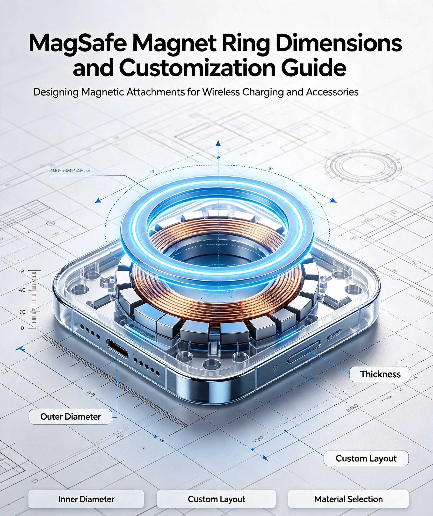
Ring Magnets (most common): OD 5–8 mm · ID 2–4 mm · thickness 1–2 mm · axially magnetized. The bore provides clearance for contact pins while the ring face concentrates field toward the mating surface.
Diametrically Magnetized Discs: diameter 4–7 mm · thickness 1–2 mm. Creates a two-pole field that snaps to a specific angular orientation — used when precise rotational locking is required.
Multi-Pole Ring Magnets: 4 or 8 alternating poles. Allows multiple valid mating orientations while preventing off-position connections — ideal for 4-pin and 6-pin connector designs.
Material Specifications
Grade: N52H is the Baseline for Fast-Charge Applications
Fast charging generates heat at the contact pins. Sustained temperatures above 60–70°C will demagnetize standard N52 over time. N52H (Hcj ≥ 1990 kA/m, rated to 120°C) is the correct grade for 65W+ applications. For 100W+ USB-PD 3.0 and proprietary fast-charge protocols, N52SH (150°C rated) should be specified.
Coating: Ni-Cu-Ni with Tight Thickness Control
Magnetic cable tips are connected and disconnected dozens of times daily. Ni-Cu-Ni triple-layer plating is standard. For premium products, electroless nickel (EN) on the mating face provides superior abrasion resistance. Total coating thickness must be controlled to 10–20 μm — excess plating on OD/ID causes assembly interference with the housing bore.
Tolerance: ±0.02 mm Required
Standard magnet production tolerance (±0.05–0.1 mm) is insufficient for press-fit housing assembly. ±0.02–0.03 mm requires laser cutting or precision centerless grinding as the final machining step.
Fast-Charging Compatibility: 100W and 240W
Higher power levels use larger connector tips (9–11 mm vs 6–7 mm for 5W), allowing proportionally larger magnets with greater pull force — improving connection security precisely where dropped connections are most costly.
Data Transmission: Does the Magnet Interfere?
A ferromagnetic pole piece (mild steel or silicon steel) concentrates the NdFeB field toward the mating face and away from signal conductors, reducing stray field at data pins by 60–80%. Properly designed magnetic connectors add no measurable signal degradation through USB 3.2 Gen 1 (5 Gbps).