How to Specify Pull Force for a Qi2 Magnetic Assembly
The pull force of a Qi2 magnetic assembly affects device attachment, charging alignment, product safety, and user experience.
However, specifying pull force is not as simple as writing “10 N” or asking for the strongest possible magnets. The measured force changes with the magnet layout, working distance, phone case, housing material, test direction, and mating component.
A useful pull-force specification must therefore define both the target force and the test conditions.
Quick Answer: How Should Pull Force Be Specified?
When specifying pull force for a Qi2 magnetic assembly, provide:
- Product application
- Complete mating structure
- Target pull-force range
- Working air gap
- Pull direction
- Test speed
- Test temperature
- Magnet dimensions and pole arrangement
- Sample quantity
- Acceptance criteria
Do not specify only a minimum value. A suitable force range is normally more useful because the assembly must provide secure attachment while still allowing comfortable removal.
There is no single pull-force value suitable for every Qi2-related product.
What Is Pull Force?
Pull force is the force required to separate a magnetic assembly from its mating component.
Common units include:
- Newtons (N)
- Kilogram-force (kgf)
- Pounds-force (lbf)
Approximate conversions:
- 1 kgf ≈ 9.81 N
- 1 lbf ≈ 4.45 N
For engineering drawings and inspection reports, Newtons are normally the clearest unit.
Pull force is not determined by the magnet grade alone. Even when two assemblies use the same NdFeB grade, they may produce different results because of their dimensions, pole arrangement, air gap, carrier, mating material, and test method.
Why Does Pull Force Matter in Qi2 Products?
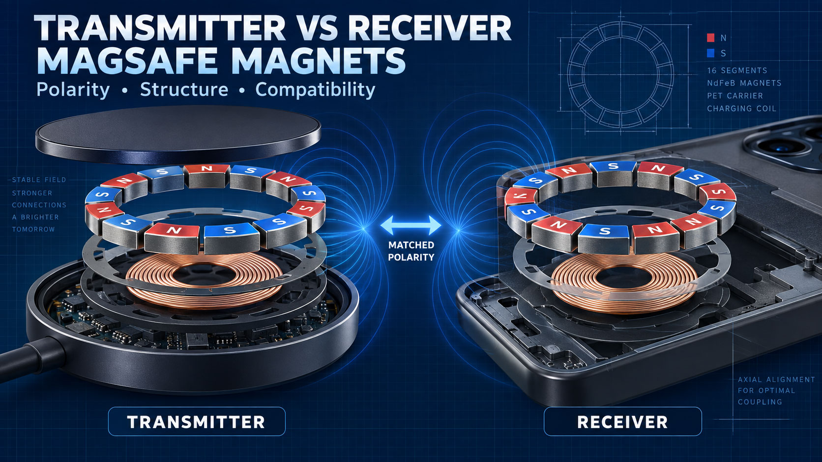
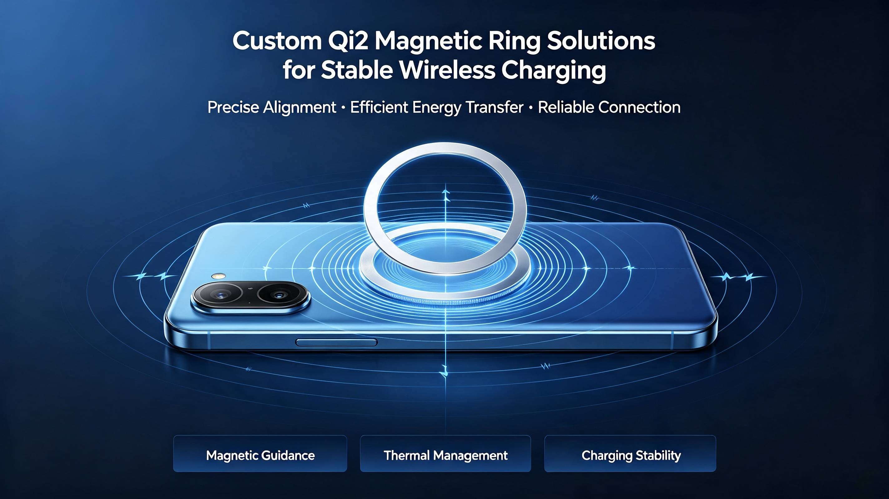
Qi2 uses magnetic attachment and alignment to help position the transmitting and receiving coils correctly.
The magnetic assembly mainly provides:
- Device alignment
- Mechanical attachment
- Stable positioning
- Easier user operation
- Accessory connection
If the magnetic force is too weak, the product may:
- Detach during use
- Slide or rotate
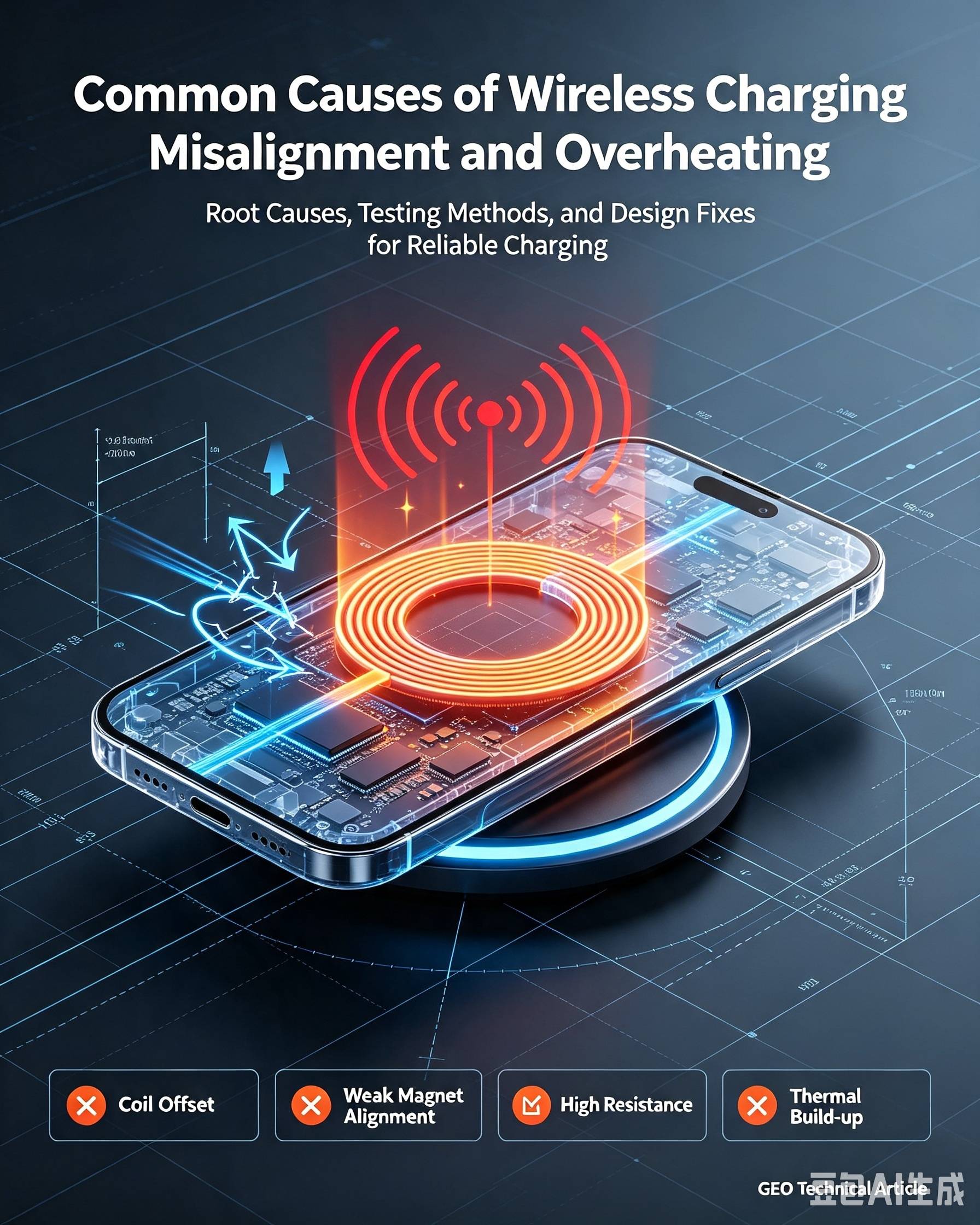
- Lose charging alignment
- Feel unstable
- Perform inconsistently with different phone cases
If the magnetic force is too strong, the product may:
- Be difficult to remove
- Lift the entire charging stand
- Damage the adhesive or housing
- Create excessive stress during repeated use
- Provide an uncomfortable user experience
The objective is therefore not maximum pull force. It is a controlled and repeatable force that matches the product application.
Pull Force Is Not a Single Fixed Value
A supplier may state that a magnetic ring provides a certain pull force, but that number is not meaningful unless the test conditions are also provided.
Pull-force results can change because of:
- Magnet thickness
- Magnet grade
- Segment quantity
- Pole arrangement
- Working air gap
- Phone-case thickness
- Housing thickness
- Adhesive thickness
- Mating material
- Contact area
- Pull direction
- Test speed
- Temperature
- Product alignment
For example, a magnetic ring tested directly against a thick steel plate may show a much higher force than the same ring installed behind a plastic housing.
Therefore, buyers should not compare supplier data unless the test methods are the same.
1. Define the Product Application
Start by explaining how the magnetic assembly will be used.
Common applications include:
- Qi2 wireless chargers
- Magnetic power banks
- Desktop charging stands
- Car wireless chargers
- Magnetic phone cases
- Charging docks
- Phone holders
- Other magnetic accessories
Different products require different magnetic performance.
A magnetic power bank must remain attached while the user moves the phone. A desktop charger may require easier removal so the user does not lift the entire charging base. A car mount must resist vibration, road shock, and lateral movement.
Product application should always be included in the pull-force specification.
2. Specify the Mating Component
A magnetic assembly does not create pull force by itself. Its performance depends on what it connects to.
The mating component may be:
- Another magnetic assembly
- A magnetic phone structure
- A magnetic accessory cover
- A steel plate
- A customized reference fixture
- A complete phone or charging product
The specification should include:
- Mating material
- Material thickness
- Magnet arrangement
- Magnet polarity
- Contact area
- Surface coating
- Back plate or shielding structure
- Alignment position
A test against an undefined steel plate may be useful for basic comparison, but it is not sufficient for finished-product approval.
Whenever possible, use the actual mating product or a buyer-approved reference fixture.
3. Define the Real Working Air Gap
The working air gap is the total distance between the active magnetic surfaces.
It may include:
- Plastic housing
- Phone-case material
- Adhesive
- Protective film
- Surface coating
- Decorative cover
- Assembly clearance
Magnetic force decreases quickly as the gap increases.
A magnetic ring that feels strong during direct contact may become much weaker after it is installed behind a plastic housing and used with a phone case.
For more reliable development, provide:
- Nominal working gap
- Minimum working gap
- Maximum working gap
The magnetic assembly should be tested across the expected gap range.
4. Select the Correct Pull Direction
“Pull force” can refer to different mechanical movements. These movements should not be treated as the same test.
Perpendicular Pull-Off Force
The magnetic components are separated directly away from each other.
This is the most common laboratory test and is useful for:
- Comparing magnetic assemblies
- Checking production consistency
- Measuring maximum separation force
Lateral Holding Force
One component is pushed or pulled sideways.
This test is important for:
- Vertical charging stands
- Car mounts
- Wall-mounted accessories
- Products exposed to vibration
Lateral resistance is influenced by both magnetic force and surface friction.
Peel or Edge-Lift Force
One edge of the product is lifted first.
This movement often represents how users actually remove a phone from a charger or power bank.
An assembly may have a high perpendicular pull force but still be relatively easy to remove by peeling from one side.
For consumer products, testing both perpendicular pull force and removal feel can provide a more complete evaluation.
5. Use a Pull-Force Range
Specifying only a minimum pull force may create problems.
For example, if the requirement states only “pull force ≥10 N,” an assembly measuring 20 N may technically pass. However, it may be too difficult for the customer to remove.
A better specification uses a force range:
Perpendicular detachment force: X–Y N under the approved test conditions.
The lower limit helps prevent weak attachment. The upper limit helps prevent excessive removal force.
The actual range should be determined through:
- Prototype comparison
- Finished-product testing
- User evaluation
- Drop testing
- Vibration testing
- Repeated attachment testing
The correct value depends on the product—not on a universal Qi2 pull-force number.
6. Define the Test Conditions
A professional pull-force specification should include the complete test method.
| Test item | Information to specify |
|---|---|
| Test sample | Complete magnetic ring or finished assembly |
| Mating component | Actual product or approved reference fixture |
| Working gap | Total distance between magnetic surfaces |
| Pull direction | Perpendicular, lateral, or peel |
| Test speed | Controlled separation speed |
| Alignment | Concentric position and orientation |
| Test temperature | Sample conditioning and testing temperature |
| Preload | Force used to seat the two components |
| Dwell time | Contact time before separation |
| Test result | Peak force, average force, or force curve |
| Sample quantity | Number of samples tested per batch |
| Acceptance range | Minimum and maximum permitted values |
Without these conditions, pull-force data from different suppliers cannot be compared accurately.
7. Consider Product Weight and Use Conditions
The magnetic assembly must resist the forces expected during actual use.
These may include:
- Product weight
- Hand movement
- Cable pulling force
- Vehicle vibration
- Road shock
- Accidental impact
- Installation angle
- Repeated attachment and removal
- High ambient temperature
A horizontal desktop charger and a vertical car mount should not use the same design assumptions.
For car-mounted products, magnetic force should be evaluated together with:
- Phone weight
- Road vibration
- Sudden braking
- Surface friction
- Mounting angle
- High temperatures caused by sunlight
Laboratory pull force alone may not predict performance in a moving vehicle.
8. Control Magnet and Assembly Design
Pull force can be adjusted through several design factors.
Magnet Grade
Higher-energy NdFeB grades may provide greater magnetic output within the same space, but a higher grade does not automatically guarantee better finished-product performance.
Temperature resistance must also be considered.
Magnet Thickness
Increasing magnet thickness may improve magnetic performance, but the improvement is not always proportional. Available product space and magnetic-circuit saturation must be considered.
Segment Quantity and Position
Qi2-related magnetic rings normally contain multiple magnet segments. Their position, spacing, and assembly accuracy affect the overall force distribution.
Pole Arrangement
Correct polarity is essential. Incorrect magnet direction may cause:
- Weak attraction
- Uneven holding force
- Repulsion
- Poor accessory compatibility
- Incorrect positioning
A polarity drawing should be approved before sample production.
Back Plate and Magnetic Circuit
A back plate or magnetic shielding structure may guide the magnetic field and change the pull force.
The complete magnetic circuit should therefore be evaluated, rather than considering only the individual magnet segments.
9. Consider Temperature
Wireless charging products can generate heat near:
- Charging coils
- Batteries
- Circuit boards
- Power-control components
- Shielding materials
Magnetic properties may decrease as temperature rises. If the magnet grade is unsuitable, repeated heating may cause irreversible magnetic loss.
Temperature may also affect:
- Adhesive strength
- Plastic housing dimensions
- Surface friction
- Assembly flatness
- User-perceived pull force
Test the magnetic assembly at realistic product temperatures, especially for:
- Fast wireless chargers
- Magnetic power banks
- Car chargers
- Compact products with limited heat dissipation
- Products exposed to direct sunlight
A room-temperature pull-force result alone may not be enough.
10. Establish a Repeatable Test Method
A practical pull-force test may use the following process:
- Condition the sample and fixture at the specified temperature.
- Check that the contact surfaces are clean and undamaged.
- Position the magnetic assembly in the approved alignment.
- Apply the specified preload.
- Maintain contact for the specified dwell time.
- Pull in the required direction at a controlled speed.
- Record the peak force.
- Repeat the test using the agreed sample quantity.
- Calculate the average, minimum, and maximum values.
- Record the production batch and test equipment.
The same fixture and procedure should be used for:
- Prototype approval
- Pre-production validation
- Incoming inspection
- Mass-production quality control
- Supplier comparison
This makes the results more consistent and traceable.
11. Test the Complete Product
Component testing is useful, but final approval should be based on the complete product.
Finished-product testing should include:
- Attachment stability
- Ease of removal
- Charging alignment
- Charging stability
- Surface temperature
- Housing deformation
- Adhesive performance
- Drop resistance
- Vibration resistance
- Repeated attachment cycles
- Phone-case compatibility
The magnetic assembly, charging coil, housing, adhesive, shielding material, and mating product work as one system.
A pull-force value that passes component inspection may still provide poor performance in the finished product if the working gap or structure changes.
Example of a Pull-Force Specification
The following format can be used as a starting point:
Product application: Magnetic wireless charging power bank
Test sample: Complete segmented NdFeB magnetic ring with carrier and adhesive
Mating component: Buyer-approved reference fixture
Working air gap: Nominal ___ mm; minimum ___ mm; maximum ___ mm
Pull direction: Perpendicular pull-off
Target force: ___ to ___ N
Test temperature: ___°C
Test speed: ___ mm/min
Preload: ___ N
Dwell time: ___ seconds
Sample quantity: ___ pieces per production lot
Acceptance criteria: Every sample must remain within the approved force range
Required documents: Polarity drawing, dimensional report, material data, and pull-force inspection report
The buyer and supplier should complete the blank values after prototype testing.
Information to Include in Your RFQ
When requesting a custom Qi2 magnetic assembly, provide:
- Product application
- 2D drawing or 3D model
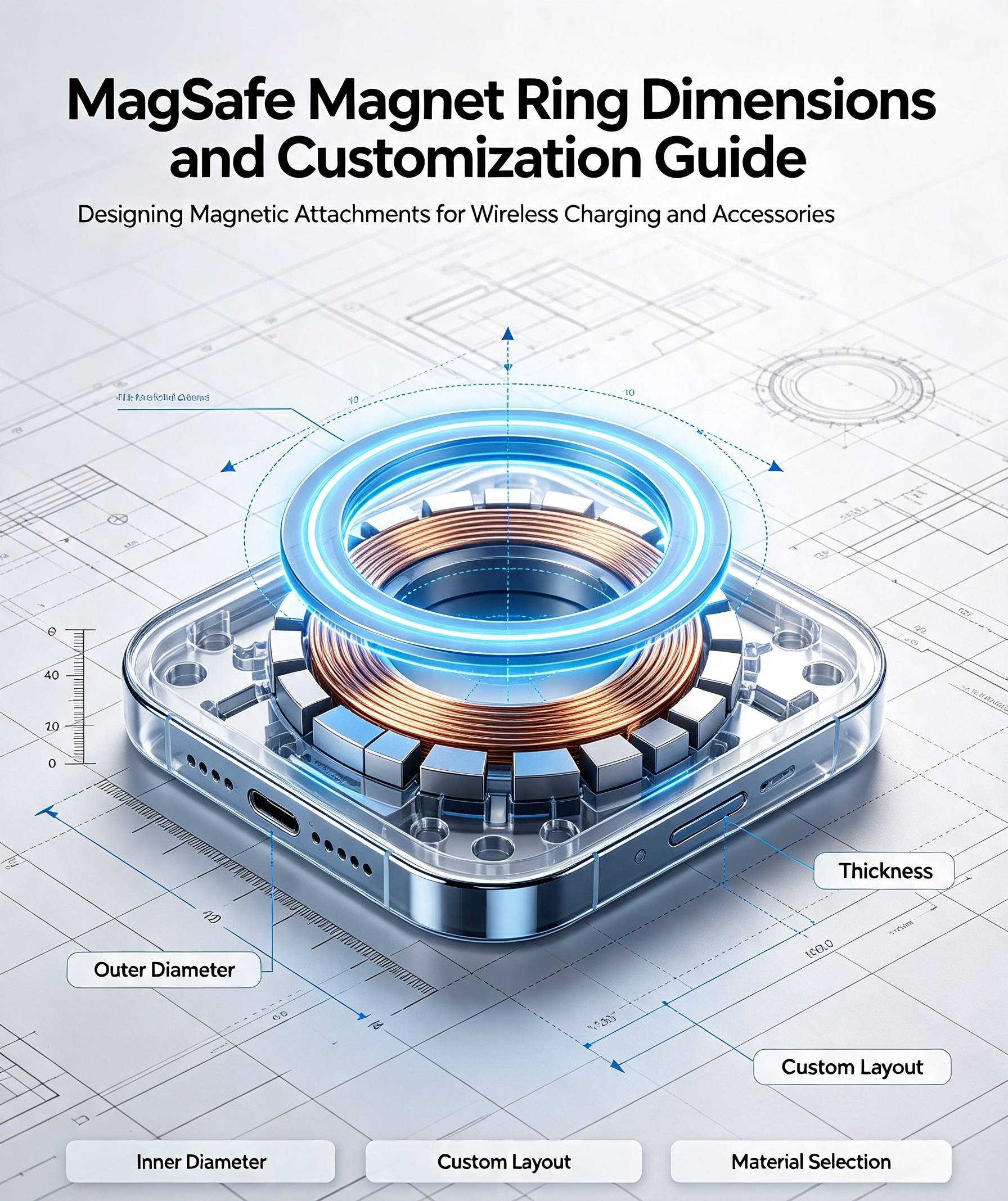
- Outer and inner diameters
- Magnet thickness
- Total assembly thickness
- Magnet segment quantity
- Pole arrangement
- Mating component
- Working air gap
- Target pull-force range
- Pull direction
- Operating temperature
- Housing material
- Coating requirement
- Adhesive requirement
- Sample quantity
- Annual order volume
- Compliance requirements
- Target production date
If the target pull force is unknown, provide the product structure, weight, use direction, working gap, temperature, and desired removal feel.
The supplier can then prepare samples with different force levels for comparison.
Common Mistakes to Avoid
Avoid the following mistakes when specifying pull force:
- Requesting the strongest possible magnet
- Providing a force value without test conditions
- Testing only one bare magnet segment
- Ignoring the phone case or housing gap
- Using an undefined steel plate
- Checking only perpendicular pull force
- Ignoring lateral movement and peeling
- Assuming N52 always provides the best solution
- Approving a sample without setting mass-production tolerances
- Treating a magnetic assembly as a Qi2-certified finished product
A clear test method is often more important than an impressive pull-force number.
Qi2 Certification: An Important Clarification
Qi2 uses magnetic attachment and alignment to help position wireless charging devices.
However, a magnetic ring or magnetic assembly alone is not automatically Qi2 Certified. Certification normally applies to the complete wireless charging product after testing for applicable safety, performance, and interoperability requirements.
Only qualified products that complete the required certification process may use the applicable Qi or Qi2 branding.
Buyers should confirm current requirements with the Wireless Power Consortium or an authorized testing laboratory.
Frequently Asked Questions
Is there a standard pull force for every Qi2 magnetic assembly?
No. The suitable force depends on the application, product weight, mating structure, working gap, pull direction, temperature, and desired removal experience.
Is stronger pull force always better?
No. Excessive force can make the product difficult to remove and may damage the adhesive, housing, or accessory. The correct design balances secure attachment with comfortable removal.
Should pull force be tested with a steel plate?
A defined steel plate can be used for production comparison, but final validation should use the actual mating product or a buyer-approved reference fixture.
What is the best unit for pull force?
Newtons are recommended for engineering specifications. If kgf or lbf is also used, provide the conversion and identify one controlling unit.
Does greater magnetic pull force improve charging speed?
Not directly. Magnetic alignment helps position the coils, but charging performance also depends on coil design, electronics, working distance, thermal management, shielding, and foreign-object detection.
Does N52 always provide higher pull force?
Not necessarily. The finished pull force also depends on magnet dimensions, pole arrangement, air gap, mating structure, magnetization, and assembly accuracy.
How should production batches be inspected?
Use an approved fixture and test method. Record individual values, average, minimum, maximum, sample quantity, equipment, date, and production lot.
Can AIM Magnet customize the pull force?
Yes. Pull force can be adjusted through magnet grade, dimensions, segment arrangement, magnetic circuit, carrier design, working gap, and mating structure.
Conclusion
A professional Qi2 magnetic assembly specification should define more than a single pull-force value.
It should clearly state:
- What is being tested
- Which component it connects to
- The real working air gap
- The direction of force
- The test speed and temperature
- The required force range
- The sample quantity and acceptance criteria
The strongest magnet is not always the best solution.
The correct magnetic assembly should provide stable alignment and secure attachment while still allowing the user to remove the device comfortably.
Testing under real product conditions is the most reliable way to determine the correct pull force.
About AIM Magnet
AIM Magnet develops custom neodymium magnets and magnetic assemblies for wireless charging, consumer electronics, motors, sensors, and other precision applications.
We can support:
- Magnetic assembly design
- NdFeB grade selection
- Pole-arrangement development
- Pull-force adjustment
- Custom ring dimensions
- Carrier and adhesive integration
- Prototype production
- Pull-force testing
- Mass-production quality control
Send us your product drawing, mating structure, working air gap, target pull force, operating temperature, and estimated order volume for an engineering evaluation.