Common Causes of Wireless Charging Misalignment and Overheating
Wireless charging offers a convenient way to power smartphones, earbuds, power banks, and other portable devices. However, poor alignment and excessive heat can reduce charging speed, interrupt power transfer, or create an uncomfortable user experience.
These problems are not caused by magnets alone. A wireless charging system includes:
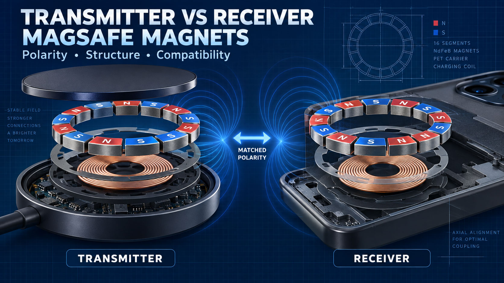
- Transmitting and receiving coils
- Magnetic alignment components
- Ferrite shielding
- Power-control electronics
- Foreign-object detection
- Product housing
- Battery and thermal-management system
A problem in any of these areas may contribute to misalignment or overheating.
This guide explains the most common causes, how magnetic assemblies affect performance, and what OEM and ODM buyers should check during product development.
Quick Answer: What Causes Wireless Charging Misalignment and Overheating?
Common causes include:
- Incorrect coil positioning
- Weak or uneven magnetic attraction
- Incorrect magnet polarity
- Excessive distance between charging coils
- Thick or incompatible phone cases
- Metal objects between the charger and device
- Poor ferrite shielding
- Inaccurate product assembly
- Excessive charging power
- Poor heat dissipation
- Incompatible chargers or power adapters
- Faulty temperature sensing
- Poor foreign-object detection
- Damaged batteries or electronic components
Misalignment and overheating are often connected. When the coils are not correctly aligned, magnetic coupling becomes less efficient. More energy may be lost as heat, and the charging system may reduce power or stop charging.
How Wireless Charging Alignment Works
Wireless charging transfers energy between two coils:
- A transmitting coil inside the charger
- A receiving coil inside the phone or device
The two coils should be positioned close to each other and aligned correctly.
When alignment is good:
- Magnetic coupling is stronger
- Energy transfer is more efficient
- Charging is more stable
- Less energy is wasted
- Temperature is easier to control
When alignment is poor:
- Charging may start and stop
- Charging speed may decrease
- The device may become warmer
- The system may repeatedly reconnect
- Foreign-object detection may behave incorrectly
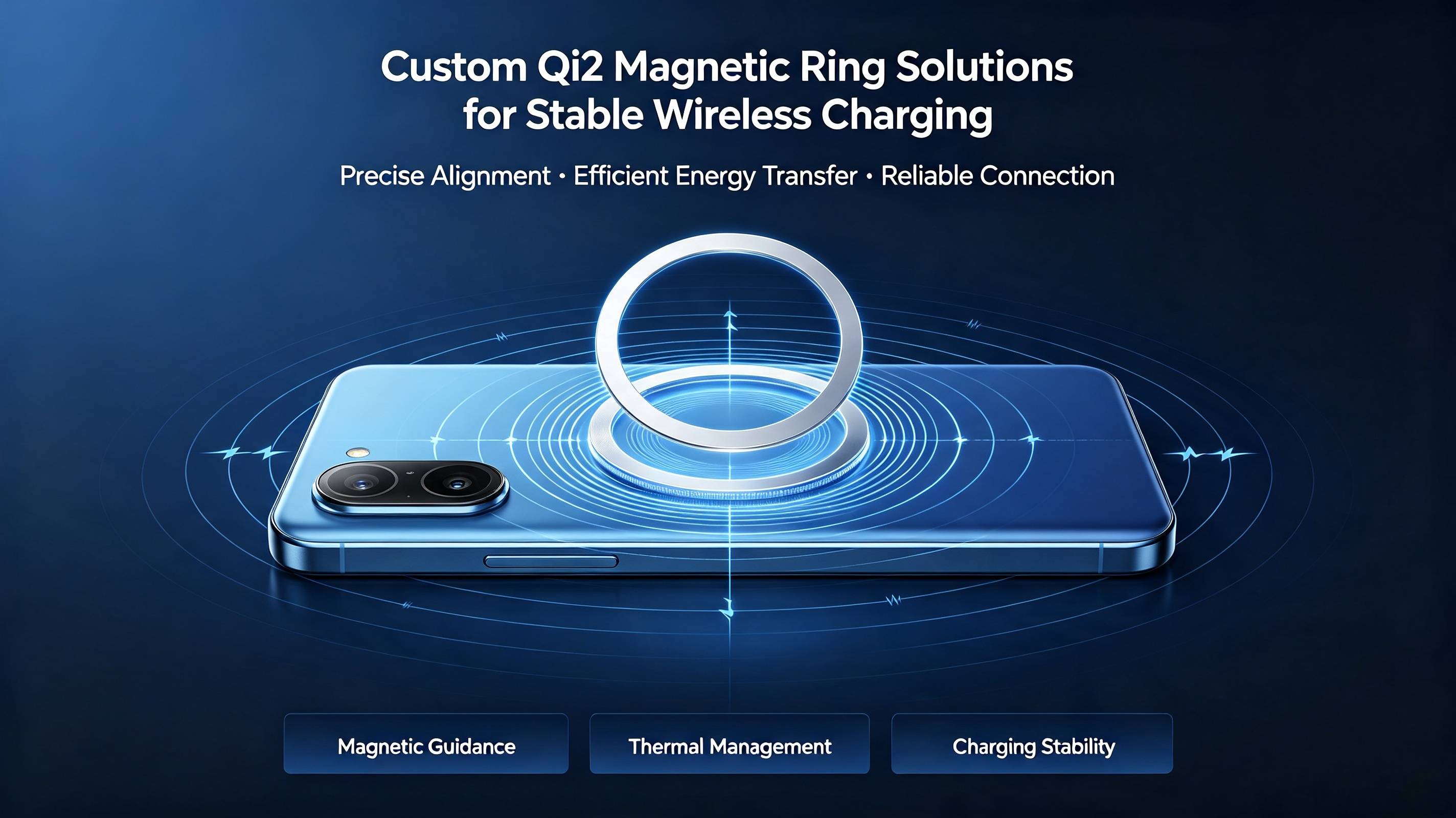
Qi2 uses magnetic attachment and alignment to help position the transmitting and receiving devices. The Wireless Power Consortium explains that this magnetic alignment improves connection, convenience, and energy efficiency. However, magnets are only one part of the complete system.
1. Incorrect Coil Position
One of the most common causes of wireless charging misalignment is an incorrect coil position.
The coil may be positioned incorrectly because of:
- Product-design errors
- Inaccurate assembly
- Housing deformation
- Incorrect adhesive placement
- Loose internal components
- Incorrect magnetic-ring position
- Poor tolerance control
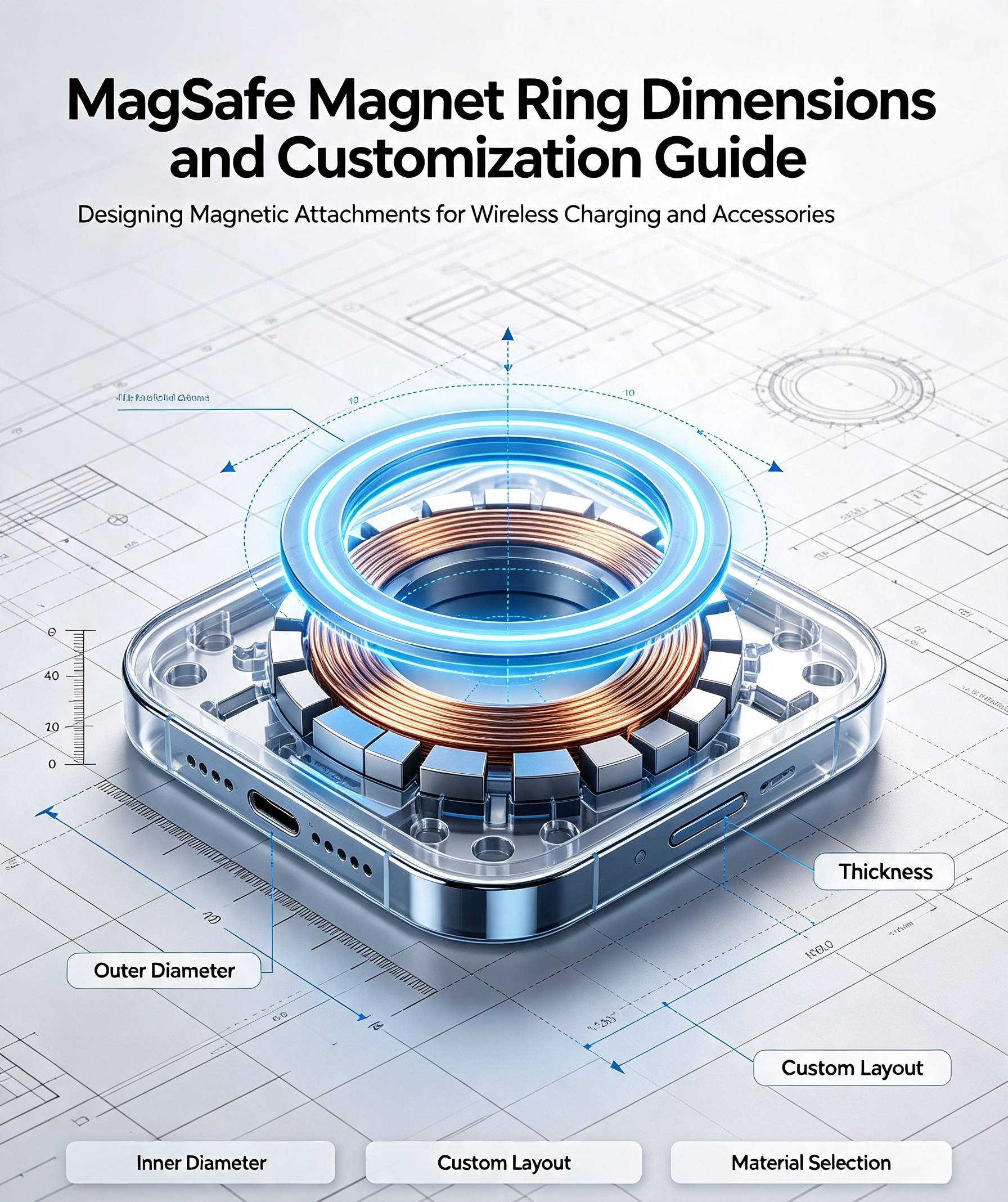
Even if the magnetic ring is correctly designed, the charging coils may still be misaligned if the ring and coil do not share the same center.
Important positional requirements include:
- Coil-to-magnet-ring concentricity
- Coil-to-housing position
- Ring-to-housing position
- Vertical distance between coils
- Orientation-magnet position
For reliable production, the drawing should use a common center datum for the charging coil and magnetic ring.
2. Incorrect Magnetic-Ring Position
The magnetic ring is intended to guide the phone or accessory into the correct charging position.
If the ring is installed off-center, the product may snap into a position where the magnets align but the charging coils do not.
This can cause:
- Reduced charging efficiency
- Higher temperature
- Unstable charging
- Slower charging speed
- Charging interruptions
The magnetic ring should therefore be positioned according to the actual coil location—not only according to the outside appearance of the housing.
Recommended inspections include:
- Optical position measurement
- Custom assembly fixtures
- Concentricity inspection
- Go/no-go gauges
- Finished-product alignment testing
3. Incorrect Magnet Polarity
A segmented magnetic ring contains multiple small magnets installed in a defined pole arrangement.
Incorrect polarity may cause:
- Local magnetic repulsion
- Weak attraction
- Uneven holding force
- Incorrect accessory positioning
- Rotation or sideways movement
- Poor compatibility with mating products
One reversed magnet segment can change the local magnetic field and make the complete assembly feel unstable.
The supplier should provide a polarity drawing before production and inspect every assembly using:
- Magnetic viewing film
- Pole-detection equipment
- Hall-effect sensors
- Custom polarity fixtures
- Automated magnetic inspection
Magnet polarity should never be confirmed only by visual inspection.
4. Weak or Uneven Magnetic Force
If the magnetic attraction is too weak, the phone may not remain in the correct charging position.
Possible causes include:
- Magnets that are too thin
- Unsuitable NdFeB grade
- Excessive working air gap
- Incorrect pole arrangement
- Uneven segment spacing
- Insufficient magnetic area
- Poor magnetization
- Missing magnet segments
- Incorrect mating structure
Uneven force can be particularly problematic because the phone may rotate or tilt even when the total pull force appears acceptable.
The supplier should evaluate:
- Complete-ring pull force
- Force distribution
- Lateral holding force
- Peel force
- Segment position
- Ring flatness
- Polarity consistency
The strongest possible magnet is not always required. The target should be stable and balanced attachment.
5. Excessive Magnetic Force
Magnetic force that is too high can also create problems.
Excessive force may:
- Make the phone difficult to remove
- Lift the entire charging stand
- Damage the adhesive layer
- Deform a thin housing
- Increase wear during repeated use
- Create an undesirable user experience
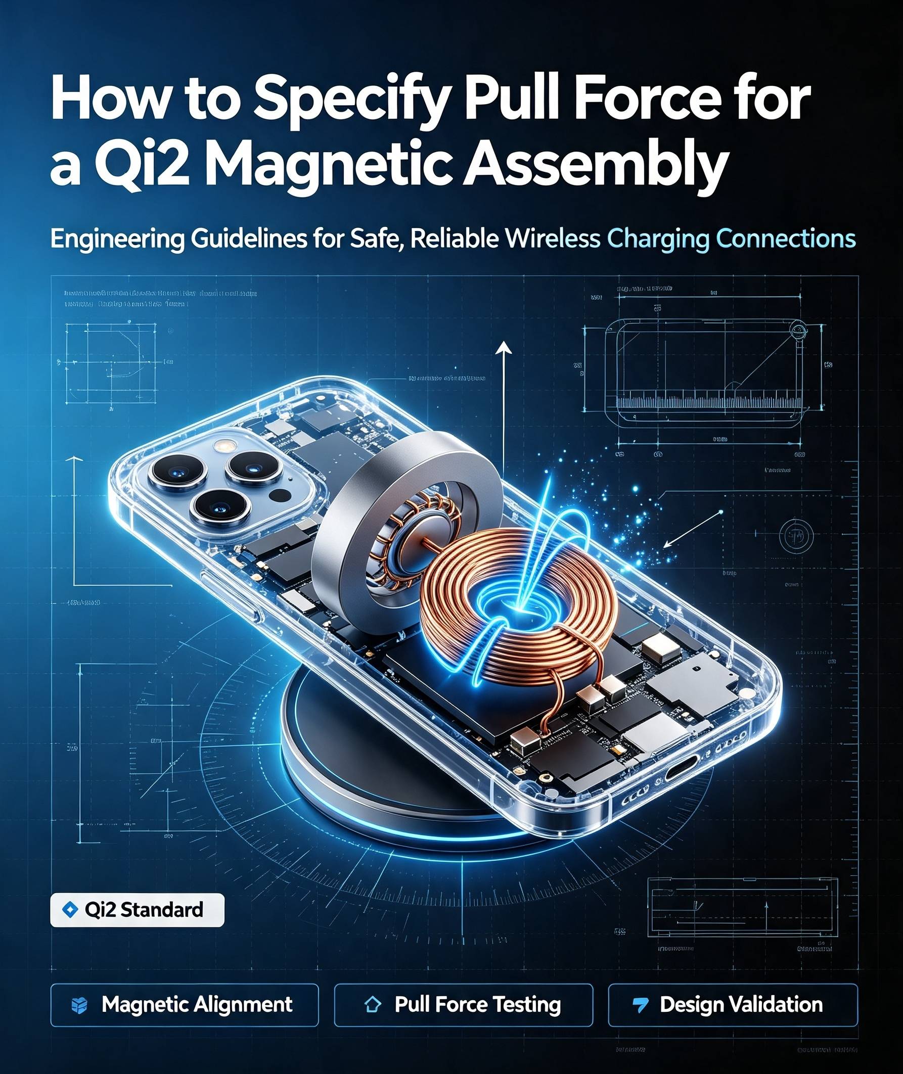
A magnetic assembly should normally use a target force range rather than only a minimum value.
Pull-force specifications should define:
- Mating component
- Working air gap
- Pull direction
- Test speed
- Temperature
- Minimum and maximum force
- Sample quantity
6. Excessive Distance Between the Coils
Wireless charging performance decreases when the distance between the transmitting and receiving coils increases.
The total working distance may include:
- Charger housing
- Phone housing
- Phone case
- Adhesive
- Protective film
- Decorative cover
- Air clearance
- Camera-related tilting
- Dust or foreign material
A thick phone case or housing can reduce both:
- Magnetic holding force
- Wireless power-transfer efficiency
The charging system may compensate by adjusting power, but excessive distance can still lead to slower charging or additional heat.
Product drawings should define the nominal and maximum coil-to-coil distance.
7. Thick or Incompatible Phone Cases
Phone cases are a common cause of consumer wireless charging problems.
Potential problems include:
- Excessive case thickness
- Incorrect magnet-ring position
- Weak magnetic material
- Metal decorations
- Steel support plates
- Misaligned magnetic rings
- Raised camera structures
- Uneven case surfaces
A case may allow charging to begin while still creating poor alignment or a large working gap.
Product testing should include:
- No case
- Original target case
- Maximum specified case thickness
- Magnetic accessory cover
- Case with camera protection
- Repeated attachment testing
A generic adhesive magnetic ring added to an incompatible case may not provide the same performance as an integrated magnetic design.
8. Camera Bumps and Uneven Contact Surfaces
Modern smartphones often have raised camera modules.
A camera bump may prevent the phone from lying flat against the charging surface. This can cause:
- Increased coil distance
- Angular misalignment
- Uneven magnetic contact
- Reduced pull force
- Local pressure points
- Charging instability
The Wireless Power Consortium added requirements related to mechanical obstructions near the charging area in later Qi specification development.
OEM designers should check:
- Camera-to-charger clearance
- Complete contact flatness
- Device tilt
- Magnet-ring location
- Charger surface shape
The charger housing may require a recessed or raised structure to maintain correct contact.
9. Metal Objects Between the Charger and Device
Metal objects inside the wireless charging field may absorb energy and become hot.
Examples include:
- Coins
- Keys
- Steel plates
- Metal phone-case inserts
- Magnetic mounting plates
- Metal decorations
- Foil labels
- Conductive debris
Possible results include:
- Localized overheating
- Charging interruption
- Reduced power-transfer efficiency
- Foreign-object-detection activation
- Damage to the phone case or accessory
Foreign-object detection is an important part of a wireless charging system, but its performance depends on system design, calibration, and test conditions.
Magnets should not be confused with random metal objects. A magnetic assembly intended for the charging system must be evaluated together with the coils, shielding, and electronics.
10. Poor Ferrite Shielding
Ferrite materials help control the magnetic field around the charging coils.
Poor shielding may cause:
- Energy loss
- Heating of nearby metal components
- Electromagnetic interference
- Reduced charging efficiency
- Unstable foreign-object detection
- Heating near the battery or PCB
Ferrite-related problems may result from:
- Incorrect material
- Insufficient thickness
- Cracks
- Gaps between ferrite pieces
- Incorrect dimensions
- Poor coil coverage
- Assembly damage
Ferrite sheets are often fragile and can crack during assembly. Even if the outside of the product looks normal, internal damage may change performance.
11. Poor Coil Design
Coil dimensions and electrical characteristics directly affect power-transfer performance.
Potential problems include:
- Incorrect coil diameter
- Improper number of turns
- High electrical resistance
- Poor-quality wire
- Inaccurate winding
- Coil deformation
- Incorrect resonant components
- Poor thermal contact
An unsuitable coil may generate more resistive heat or provide poor coupling even when it appears correctly aligned.
Coil design should be evaluated together with:
- Operating frequency
- Resonant circuit
- Input power
- Receiver requirements
- Shielding
- Thermal limits
The magnet supplier normally does not control the complete charging circuit, so coil and electronics validation must involve the relevant engineering team.
12. Excessive Charging Power
Higher charging power can increase thermal stress.
Heat may be generated by:
- Coil resistance
- Power-conversion losses
- Battery charging
- Control electronics
- Misalignment
- High ambient temperature
Wireless charging systems should manage power according to device condition and temperature.
If the product attempts to maintain high power while alignment or cooling is poor, the temperature may rise quickly.
The system should be tested under:
- Maximum rated power
- Long charging periods
- High ambient temperature
- Low battery state
- Nearly full battery state
- Thick phone cases
- Slight misalignment
- Repeated charging cycles
13. Poor Heat Dissipation
Even an efficient wireless charging system generates some heat.
Poor thermal design may trap this heat inside the product.
Common causes include:
- Thick plastic housing
- No thermal path
- Small internal space
- Battery close to the coil
- Insulating adhesive
- Insufficient ventilation
- High-power components placed together
- Soft surfaces blocking airflow
- Direct sunlight
Car wireless chargers are particularly challenging because they may experience:
- High cabin temperature
- Sunlight exposure
- Continuous navigation use
- Simultaneous charging and data processing
- Limited airflow
Thermal design may require:
- Heat spreaders
- Thermal pads
- Metal frames
- Improved component layout
- Ventilation
- Active cooling
- Power reduction at high temperatures
14. High Ambient Temperature
The surrounding environment has a strong influence on charging temperature.
Examples include:
- Cars parked in sunlight
- Outdoor charging
- Devices under blankets or pillows
- Chargers placed near heat sources
- Hot production environments
A product that performs well at room temperature may behave differently at a high ambient temperature.
High temperature can affect:
- Battery charging behavior
- Magnet performance
- Adhesive strength
- Plastic dimensions
- Electronic efficiency
- Thermal-protection response
Testing should measure the temperature at critical internal locations—not only on the outside surface.
15. Incompatible Power Adapter or Cable
The charger’s input power also affects system stability.
Possible problems include:
- Insufficient adapter power
- Unstable voltage
- Poor-quality cables
- High cable resistance
- Unsupported charging protocols
- Damaged connectors
- Counterfeit power adapters
These problems may cause:
- Repeated charging connection
- Reduced charging speed
- Electronic-component heating
- Unexpected power negotiation
- System shutdown
Testing should use the specified power adapter and cable, as well as representative compatible alternatives.
16. Poor Foreign-Object Detection
Foreign-object detection, commonly called FOD, helps identify unwanted conductive objects in the charging field.
Poor FOD performance may result from:
- Incorrect calibration
- Component variation
- Mismatched coils
- Changed ferrite structure
- Metal inside the housing
- Unexpected magnetic components
- Software errors
- Excessive mechanical tolerance
FOD should be validated in the complete product after any change to:
- Magnet ring
- Coil
- Ferrite
- Housing
- Back plate
- Adhesive
- Metal components
- Firmware
Passing one component test does not prove that the complete system will detect every foreign object correctly.
17. Incorrect Magnet Material or Temperature Grade
Neodymium magnets can lose magnetic performance as temperature rises.
If the grade does not provide sufficient resistance to irreversible demagnetization, repeated exposure to heat may reduce holding force.
Possible results include:
- Weaker attachment after long-term use
- Increased misalignment
- Different performance between new and aged products
- Greater sensitivity to phone-case thickness
Standard N grades may be suitable for controlled temperatures, while higher-coercivity grades such as H or SH may be considered for products with greater thermal risk.
However, a high-temperature magnet grade does not solve poor thermal design. The actual magnet temperature and magnetic circuit must be evaluated.
18. Adhesive Movement or Failure
The magnetic ring and charging coil may be correctly positioned during initial assembly but move later because of adhesive failure.
Possible causes include:
- Incorrect adhesive selection
- Contaminated bonding surface
- Insufficient assembly pressure
- Inadequate dwell time
- High temperature
- Humidity
- Repeated mechanical stress
- Incompatible housing material
Movement of the ring, coil, or ferrite can create misalignment after the product has entered service.
Adhesive testing should include:
- High-temperature aging
- Temperature cycling
- Humidity exposure
- Peel strength
- Shear strength
- Drop testing
- Repeated attachment cycles
19. Manufacturing Tolerance Accumulation
Each component may be within its own tolerance, but the combined product may still become misaligned.
Tolerance accumulation may involve:
- Coil position
- Magnet-ring position
- Carrier dimensions
- Housing dimensions
- Adhesive thickness
- Ferrite position
- Camera-bump height
- Assembly fixture accuracy
For example, if both the coil and magnetic ring are allowed to move in opposite directions, their relative misalignment may become larger than either individual tolerance.
A tolerance-stack analysis should therefore evaluate the worst-case complete assembly.
20. Damaged or Aging Components
Overheating is not always caused by the magnetic design.
Other possible causes include:
- Aging battery
- Damaged battery
- Faulty charging circuit
- Damaged coil
- Cracked ferrite
- Loose connector
- Water damage
- Software or firmware problems
- Repeated mechanical impact
If a product becomes unusually hot, swells, smells abnormal, or repeatedly stops charging, it should no longer be used until it has been inspected by a qualified service provider.
Misalignment and Overheating: Cause-and-Effect Summary
| Problem | Possible result |
|---|---|
| Coil centers do not match | Reduced coupling and additional heat |
| Magnetic ring installed off-center | Phone attaches in the wrong charging position |
| Incorrect polarity | Uneven attraction or repulsion |
| Excessive working gap | Weak magnetic force and lower transfer efficiency |
| Metal foreign object | Localized heating and charging interruption |
| Damaged ferrite | Energy loss and heating near metal components |
| Poor thermal path | Heat remains inside the charger or phone |
| Excessive charging power | Greater thermal stress |
| High ambient temperature | Reduced cooling capacity |
| Adhesive movement | Coil or magnet position changes over time |
How to Diagnose the Problem
A structured diagnosis should separate magnetic, mechanical, electrical, and thermal causes.
Step 1: Check Mechanical Alignment
Inspect:
- Ring position
- Coil position
- Housing flatness
- Camera clearance
- Product tilt
- Case thickness
- Orientation-magnet position
Step 2: Check Magnetic Performance
Measure:
- Complete-ring pull force
- Lateral holding force
- Polarity
- Segment position
- Ring concentricity
- Working air gap
Step 3: Check Charging Performance
Record:
- Input and output power
- Charging speed
- Connection interruptions
- Coil communication
- Power reduction
- FOD response
Step 4: Measure Temperature
Measure temperature at:
- Transmitting coil
- Receiving coil
- Battery
- Power electronics
- Magnet ring
- Ferrite
- Product surface
A thermal camera can help identify hot spots, but contact sensors may be needed for accurate internal measurements.
Step 5: Compare Different Conditions
Test:
- With and without a phone case
- At room and high ambient temperature
- At different alignment positions
- With approved and alternative adapters
- At different charging power levels
- With and without magnetic accessories
Changing one condition at a time helps identify the main cause.
How Magnetic Assembly Design Can Help
A correctly designed magnetic assembly can improve:
- Coil alignment
- Attachment consistency
- User positioning
- Resistance to sliding
- Accessory compatibility
- Repeatable product assembly
Important design factors include:
- Correct ring diameter
- Accurate concentricity
- Suitable magnet thickness
- Controlled pole arrangement
- Stable carrier
- Correct orientation magnet
- Suitable holding-force range
- Heat-resistant magnet grade
- Low and controlled working gap
However, the magnetic assembly cannot correct every charging problem. Coil design, electronics, shielding, firmware, battery condition, and thermal management must also be properly engineered.
Information to Provide to a Magnetic Assembly Supplier
For a custom wireless charging magnetic assembly, provide:
- Product application
- 2D drawing or 3D model
- Charging-coil position
- Ring outer and inner diameters
- Available thickness
- Mating magnetic structure
- Working air gap
- Target pull-force range
- Pole arrangement
- Maximum operating temperature
- Housing material
- Adhesive requirement
- Expected charging power
- Sample quantity
- Annual order volume
- Required tests
- Certification target
If the exact magnetic specification is unknown, provide the complete product structure and performance problem. An experienced supplier can help evaluate whether the magnetic assembly contributes to the issue.
Frequently Asked Questions
Why does wireless charging become hot when the phone is misaligned?
Misalignment reduces magnetic coupling between the transmitting and receiving coils. The system may transfer energy less efficiently, and part of the energy may be lost as heat. The charger may reduce power or stop charging if temperature or communication limits are reached.
Can a weak magnet cause wireless charging to overheat?
Indirectly, yes. If weak attraction allows the phone to move away from the correct coil position, charging efficiency may decrease and temperature may rise. However, overheating may also come from coils, electronics, batteries, metal objects, or poor heat dissipation.
Can magnets themselves generate charging heat?
Permanent magnets do not produce wireless charging power. Most charging heat comes from electrical resistance, power-conversion loss, the battery, poor coupling, nearby conductive materials, and thermal conditions.
Does a stronger magnet solve misalignment?
Not always. Stronger magnets cannot correct an off-center ring, incorrect polarity, wrong coil position, excessive air gap, or incompatible mating structure. Accurate magnetic design is more important than maximum force.
Can a thick phone case cause overheating?
It can increase the distance between charging coils and interfere with alignment. This may reduce efficiency and increase temperature. Cases containing metal plates or misaligned magnet rings can create additional problems.
Why does the charger become hot even when alignment is correct?
Possible causes include high charging power, coil resistance, power-conversion loss, poor ventilation, high ambient temperature, battery heat, inadequate shielding, or faulty components.
Can a metal mounting plate be used with wireless charging?
A metal plate placed in the active charging area may absorb energy and become hot. It may also trigger foreign-object detection. Any conductive structure near the coil must be evaluated as part of the complete design.
Does Qi2 completely eliminate misalignment?
Qi2 magnetic alignment helps position compatible devices more accurately, but product design, mechanical obstruction, cases, component tolerances, and damage can still affect alignment.
How should overheating be tested?
Test at maximum power, high ambient temperature, different alignment positions, different battery levels, maximum approved case thickness, and extended charging time. Measure internal hot spots as well as surface temperature.
Can AIM Magnet help solve wireless charging misalignment?
AIM Magnet can evaluate the magnetic ring dimensions, pole arrangement, pull force, working air gap, magnet grade, carrier, and assembly tolerances. Electronic and Qi2 certification testing should still be completed by the appropriate engineering team or authorized laboratory.
Conclusion
Wireless charging misalignment and overheating normally result from the interaction of multiple factors.
The most common causes include:
- Incorrect coil or magnet-ring position
- Weak or uneven magnetic force
- Incorrect magnet polarity
- Excessive working distance
- Thick or incompatible phone cases
- Metal foreign objects
- Poor ferrite shielding
- High charging power
- Poor heat dissipation
- Manufacturing tolerances
A professional investigation should evaluate the complete system rather than blaming only the magnet, charger, or battery.
A well-designed magnetic assembly helps maintain accurate alignment and stable attachment, but it must work together with the charging coil, shielding, electronics, housing, and thermal-management system.
The most reliable solution is to test the complete product under real operating conditions.
About AIM Magnet
AIM Magnet develops custom neodymium magnets and magnetic assemblies for wireless charging, consumer electronics, motors, sensors, and other precision applications.
We can support:
- Magnetic-ring dimension optimization
- Magnet-grade selection
- Pole-arrangement design
- Pull-force adjustment
- Ring-to-coil alignment evaluation
- Orientation-magnet customization
- Carrier and adhesive integration
- Prototype production
- Polarity and dimensional inspection
- Mass-production quality control
Send us your product drawing, coil position, magnetic structure, working air gap, target holding force, operating temperature, and problem description for an engineering evaluation.